 OK then, it's a new month and it's time to get this car back on the road, or
at least to start fettling it so that I can get closer to that.
OK then, it's a new month and it's time to get this car back on the road, or
at least to start fettling it so that I can get closer to that.
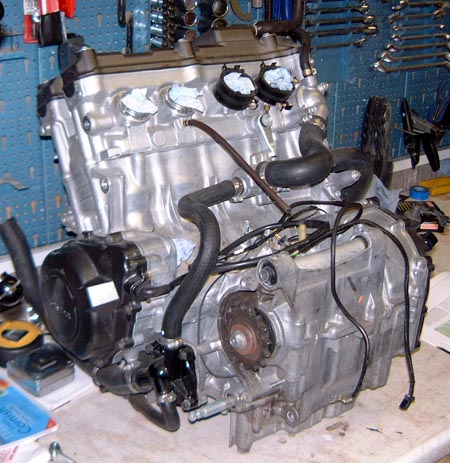
The first thing that's needed is a new engine. After the disaster I spoke to Martin and he said that they had a whole bunch of engines in stock at the moment. Rather than hunting around I decided to just go and see what I could get off him and the answer is this RRW engine here. (My other engine was one year younger, an RRX, but I think the spec is identical.) I got the engine cheaper than otherwise as I didn't need various ancillaries such as the starter motor and carbs. Hopefully the ones I've got will be fine. If nothing else this new engine is nice and shiny!
I'd sort of forgotten how tiny these engines were. I just picked up this engine out of the back of my car and put it on the bench as here. It's still sort of amazing that they work so well, clunking apart.
The first thing I did with the engine was to drain out the oil. This had obviously been used but it looked OK, so hopefully this engine has been looked after OK. I'll have a look around inside it before I put it in the car, and fit various things like the baffled sump while it's on the bench which will make life a bit easier.
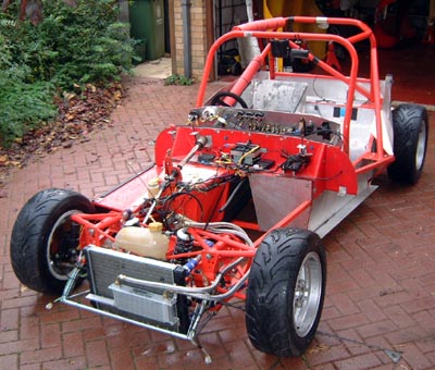 Next, I took out the old engine, which was pretty easy to do. Although it would
have been possible to just lift it out I did use the engine hoist so as to make certain I didn't drop it and break
some bit on the car. While taking it out it became obvious just how grotty the car was, especially as a result
of the oil leaks, so I decided I was going to clean it all up now I had the chance. I wondered how to do this for
a while and eventually pushed it out onto the drive and set about it with a pressure washer with a lot of detergent
in it.
Next, I took out the old engine, which was pretty easy to do. Although it would
have been possible to just lift it out I did use the engine hoist so as to make certain I didn't drop it and break
some bit on the car. While taking it out it became obvious just how grotty the car was, especially as a result
of the oil leaks, so I decided I was going to clean it all up now I had the chance. I wondered how to do this for
a while and eventually pushed it out onto the drive and set about it with a pressure washer with a lot of detergent
in it.
I wasn't too sure how well this would work but the end result seems fine, apart from the couple of bits that I missed, such as underneath the top chassis rails and under the radiator at the front.
With the engine out I should be able to get at things rather easier for any winter upgrades, about which I've got a few ideas.
 However, before getting on with that I think I'll strip the old engine.
This is for two reasons really: to get a bit of experience at taking these engines apart and to extract any bits
that I might be able to use in the future.
However, before getting on with that I think I'll strip the old engine.
This is for two reasons really: to get a bit of experience at taking these engines apart and to extract any bits
that I might be able to use in the future.
So, I got stuck in and just about the first thing I did was take off the sump and this is the carnage that greeted me. ("Hello", it said...)
All those bits seem, though, to be bits of piston. Apart from the two big end bolts that are also there. I shall have to take some care about cleaning up the oil pickup as there's bound to be quite a lot of swarf in there as a result of all this.
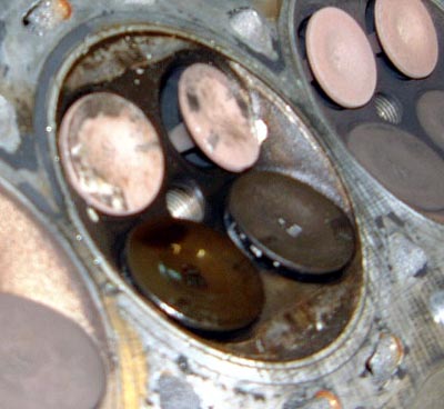
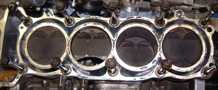 After that I took the head off and this is what I found. Eagle-eyed readers will notice
that there's something odd about number 3 piston. It's not supposed to have that hole in it, nor is it supposed
to be in a different position from number 2.
After that I took the head off and this is what I found. Eagle-eyed readers will notice
that there's something odd about number 3 piston. It's not supposed to have that hole in it, nor is it supposed
to be in a different position from number 2.
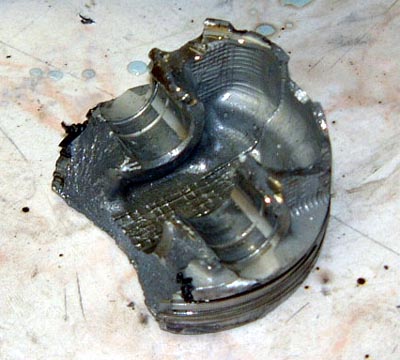 In fact, I could just poke my finger into the hole and hoick it out if the cylinder bore,
which is pretty bashed up, presumably as a result of the rod flailing about. The rather sorry remains of the piston
are shown here, you can at least see where the gudgeon pin used to be...
In fact, I could just poke my finger into the hole and hoick it out if the cylinder bore,
which is pretty bashed up, presumably as a result of the rod flailing about. The rather sorry remains of the piston
are shown here, you can at least see where the gudgeon pin used to be...
The rod attached to this pin, and the pin, seems to have just disappeared. I've got lots of bits of piston and the bearing cap from the rod but the thing in question is presumably still in Leicestershire.
 Obviously that hole in the piston had to be caused by something and on looking at the bottom of the
head these two bent exhaust valves are the obvious culprit. The exhausts are at the top, the inlets are the bottom
are just open a bit.
Obviously that hole in the piston had to be caused by something and on looking at the bottom of the
head these two bent exhaust valves are the obvious culprit. The exhausts are at the top, the inlets are the bottom
are just open a bit.
However, this head is recoverable with a couple of new valves, a bit of machining, perhaps, of the valve and possibly a couple of new guides.
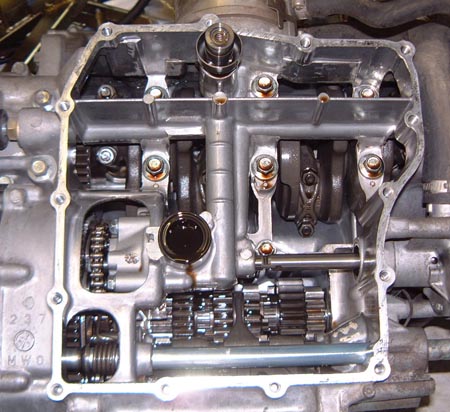
 After that I carried on taking everything to bits and it all looked pretty good. This photo shows the
main crankcase split apart so that the crank and transmission can be taken out.
After that I carried on taking everything to bits and it all looked pretty good. This photo shows the
main crankcase split apart so that the crank and transmission can be taken out.
As far as I can tell, the gearbox is fine and I shall take some care to keep these shafts, and the selector mechanism, in case they're needed again. The gearboxes seem to be the weak bit of these engines but this one looks fine.
The clutch, too, looked fine and the plates, although worn, were within tolerance as were the springs. However, I shall probably look at the clutch in the new engine to check what that's like.
 Eventually I had the engine all over the garage floor like this. I shall retain a lot of
this for spares but I guess things like the crankcase will just have to be thrown away.
Eventually I had the engine all over the garage floor like this. I shall retain a lot of
this for spares but I guess things like the crankcase will just have to be thrown away.
One observation after all this is the astonishingly high quality of all the engine components. Although everything's tiny it's clearly manufactured to a very high standard. Even the fasteners seem to have a gorgeous, but probably unnecessary level of finish.
The Rover V8 in the Rush was a completely different kettle of fish...
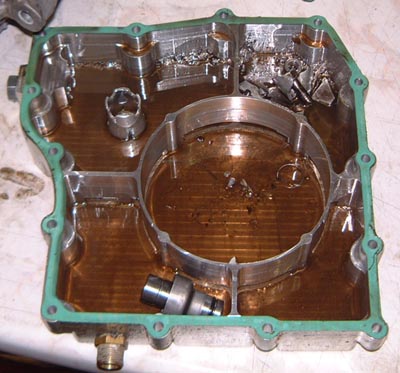
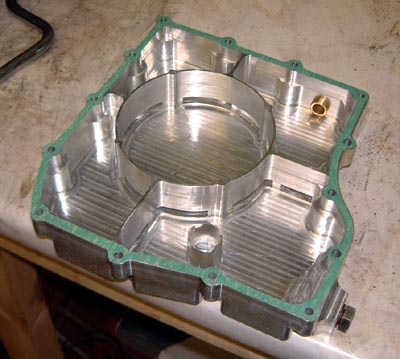 Yesterday I set about cleaning up the baffled sump and eventually got it back to looking
like this. This took ages and was mainly performed by using large quantities of Shell Optimax (it's a race car,
you see) to flush all the grot out. There's an awful lot of nook and crannies in there where little bits of swarf
accumulate. Even worse was the pick up through which I must have flushed about 3 litres of fuel.
Yesterday I set about cleaning up the baffled sump and eventually got it back to looking
like this. This took ages and was mainly performed by using large quantities of Shell Optimax (it's a race car,
you see) to flush all the grot out. There's an awful lot of nook and crannies in there where little bits of swarf
accumulate. Even worse was the pick up through which I must have flushed about 3 litres of fuel.
 I fitted this to the engine, after I'd had a good nose around inside this new
engine. The gearbox inside this one does look a little bit more worn than the old one but not to any appreciable
level.
I fitted this to the engine, after I'd had a good nose around inside this new
engine. The gearbox inside this one does look a little bit more worn than the old one but not to any appreciable
level.
Once fitted I added the other ancillaries to the engine that are best added now. Essentially this means the starter motor, sprocket adapter and the engine mountings.
So, with the engine now in a state where it's ready to be fitted (I might even take it off the bench.) it was time to look to the car. First job was to tidy up the engine compartment wiring slightly which has been annoying me recently. Once this is done then I will start looking at two of the things that I want to do.
First of these is to look into moving the pedal box a bit further forward. If I can do this it will enable me to get down a bit lower in the car which will be useful. However, in order to do this I will have to cut out the front of the pedal box and weld in some steel to move the front of the box forward a bit (I reckon that about 25mm is feasible). Obviously, this means changing the brake lines and so on which is all a bit of a fiddle but should be worthwhile in the long run. The only problem is that I don't really know whether I'll like it and it's a bit difficult to test it out without actually doing it. The other problem is that will really mean that I ought to change the roll cage and if nothing else that will be expensive. Not as expensive as a new engine though..
The other thing is to look into engineering a column paddle change. My original intention here had been to use a rod and rosejoint linkage as I had become convinced that the cable change was giving a bit too much drag. However, I now think the problem with the old gearbox was probably the gearbox actuator which, when removed it, had developed rather a lot of play. It had been a real fiddle to make it work, and it was a bit of a last moment addition. I now think I can see rather better how to do it, and to avoid using the alternator mounted bracket that I had to fabricate before by bringing the change across under the propshaft. I'll need to check carefully on the actuation angles and so on though. One problem with using a cable is that you can't use a bellcrank to change the lever ratio, you therefore have to use the levers on the end of the cable and you're limited in the cable throw. So, some careful design work is going to be needed...
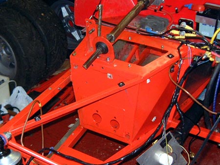 After thinking about it for a while I decided I was just going to have to hack the front
out of the pedal box just to see how it would be with the pedal a smidgeon further forward. So, I took out quite
a few bits and pieces, such as the pedals, brake master cylinders, brake fluid reservoir and so on until it looked
like this photo.
After thinking about it for a while I decided I was just going to have to hack the front
out of the pedal box just to see how it would be with the pedal a smidgeon further forward. So, I took out quite
a few bits and pieces, such as the pedals, brake master cylinders, brake fluid reservoir and so on until it looked
like this photo.
I then set about it with an angle grinder until it looked...
 ...like this.
What I now need is to get some steel of a suitable size so that I can weld it into place in front of this, I shall use the existing front plate, as that's got the mounting holes for the master cylinders and just space it forward a bit.
I need to be careful that the pedal box doesn't actually get any narrower as a result of doing this. It's fairly tight down there for my size 12s as it is and I don't want to make it any more difficult. What I shall do is weld an extension onto the floor of the box first and then look into positioning the pedals. I can then build up the box around that after making sure that my feet do actually fit.
 With that I moved onto the gearchange which is the other big modification planned.
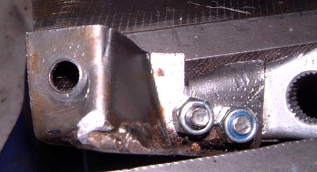
I had a more careful look at the old actuator and noticed another reason why it had been working less well. The
actuator was made (in rather a rush) with a steel bracket bolted onto a cut-down version of the aluminium actuator
that is the standard Honda part.
With that I moved onto the gearchange which is the other big modification planned.
I had a more careful look at the old actuator and noticed another reason why it had been working less well. The
actuator was made (in rather a rush) with a steel bracket bolted onto a cut-down version of the aluminium actuator
that is the standard Honda part.
What was apparent in looking at it was that the steel part had fracturedy. You can just see this fracture at the top of this photo. I'm not sure how much difference this would have made but this, and the small amount of movement that was apparent in the bolts, also in the photo, makes me think that I need to use some different technique for the actuator this time.
One big problem with doing the gearchange like the original approach is that, due to the proximity of the water pump and so on, the end of the lever where the cable attachesis not in line with the selector shaft itself. Hence there is some out of line torque and it's easy to see how the lever could fail in the way that this original one did.
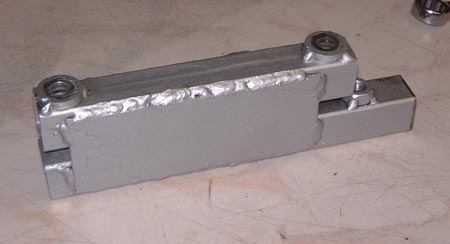
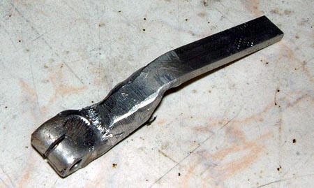 So, as an experiment I thought I would try welding an aluminium extension onto
this same actuator lever (I've actually got a spare now) in such a position where it could be used projecting the
other way: under the propshaft towards the right of the car.
So, as an experiment I thought I would try welding an aluminium extension onto
this same actuator lever (I've actually got a spare now) in such a position where it could be used projecting the
other way: under the propshaft towards the right of the car.
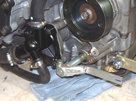 This was actually fairly successful and when on the engine it would look like
this.
This was actually fairly successful and when on the engine it would look like
this.
You can see how close the water pump is in the other direction and also where the propshaft will go from the position of the sprocket adapter above.
This sort of attachment, though, has a couple of problems. One is that even if my welding is perfect (and that's pretty unlikely in aluminium) then aluminium is subject to fatigue failure by cracking which is exactly what you don't want in this component. I suppose, though, that the steel bracket also failed, or was failing, in this manner.
The other problem is that by lengthening the lever arm the travel of the gearchange effector, however it is done, is increased. Measurements (that's what the blue line on the arm is for) indicate that at this sort of length the travel of the effector is of the order of ± 25mm, that is, a total travel of about 50mm. For a cable change that isn't really feasible. The cable I have at the moment has a travel of 38mm. There are push/pull cables with travel in excess of this but they are disturbingly chunky affairs.
This means that I'm now being pulled towards using some sort of rod and rosejoint approach to the gearchange.
I've also been putting a lot of thought into how to design the lever behind the steering wheel. There seem to be a couple of obvious designs. One of these only has one bearing at the bottom, under the steering column. The other needs something above and below the column. There are current RGB cars with both approaches and I can't quite work out which is best at the moment.
I will do though. I've got a sort of daemon process running at the back of my head which is thinking about all this. Not sure whether it's ever going to complete though....
 Well, after a lot of thought and a lot of trigonometry, I've ended up thinking
that some sort of rod change is the only way to work the gear change. So, I've got a sort of tentative design taking
place and have bought some of the bits and pieces I need, such as actuator rods, bearings and a couple of expensive
taps.
Well, after a lot of thought and a lot of trigonometry, I've ended up thinking
that some sort of rod change is the only way to work the gear change. So, I've got a sort of tentative design taking
place and have bought some of the bits and pieces I need, such as actuator rods, bearings and a couple of expensive
taps.
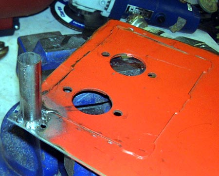
However, for now the thing to do is to get the pedal box back together. First of all, I got hold of some steel tubing and welded a bit into the front of the pedal box front cover so that I could avoid using the aluminium tubing that I previously used which was bolted, in a rather inaccessible position, to the front of the pedal box. This steel approach means that the chassis now has the thing on it that it's supposed to have anyway.
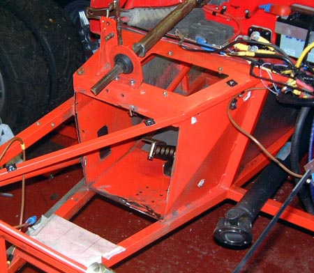
 However, it's not exactly on the chassis at the moment, or it wasn't when I took the photo
up there. Since then I've cut out some steel to extend the floor of the pedal box and drilled and ground stuff
about so that the pedals now fit about 28mm further forward than they did before. Preliminary investigations (that
is, climbing in and out of the chassis) indicate that this will provide a worthwhile modification, although it
exacerbates the issue with the roll cage being the wrong size and shape.
However, it's not exactly on the chassis at the moment, or it wasn't when I took the photo
up there. Since then I've cut out some steel to extend the floor of the pedal box and drilled and ground stuff
about so that the pedals now fit about 28mm further forward than they did before. Preliminary investigations (that
is, climbing in and out of the chassis) indicate that this will provide a worthwhile modification, although it
exacerbates the issue with the roll cage being the wrong size and shape.
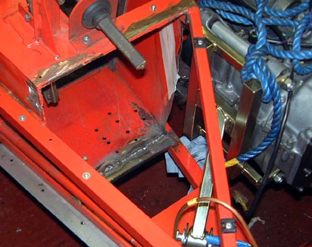
As you can see in the photo, in order to work out where everything was going to have to go, I temporarily put the engine into the chassis. Luckily it's very easy to get in and out. I remember the engine in the Dax taking hours to lift out and replace. This one's positively trivial in comparison.
 With the floor extended I welded the front of the pedal box back into position.
By this time I had taken the engine out again but I left the engine mounting bracket behind with which to check
the clearance between it and the modified pedal box.
With the floor extended I welded the front of the pedal box back into position.
By this time I had taken the engine out again but I left the engine mounting bracket behind with which to check
the clearance between it and the modified pedal box.
At one point I got a bit concerned that the pedal box might get too narrow at the end, as it essentially tapers towards the front of the car. I attempted to alleviate this problem by remodelling slightly the left hand side of the pedal box but I can't admit to being too proud of the end result. It's only the lack of some suitable steel that's stopped me cutting the entire side out of the box and welding a new plate in. That and the fact that every modification like this will increase the weight of the car.
 Finally, for now, I bent up a chunk of steel to make and extension of the top of the pedal box and
welded it in. Things are now starting to look more purposeful and a couple more evenings of metal bashing should
see integrity reinstated in this area. I'll then have to look into painting everything in this area as an inevitable
consequence of all this bashing is that the powder coating is slightly degraded now.
Finally, for now, I bent up a chunk of steel to make and extension of the top of the pedal box and
welded it in. Things are now starting to look more purposeful and a couple more evenings of metal bashing should
see integrity reinstated in this area. I'll then have to look into painting everything in this area as an inevitable
consequence of all this bashing is that the powder coating is slightly degraded now.
I did check, by the way, that the master cylinders still clear the engine mounting bracket...
 I finally managed to get around to cutting out the last piece of steel and welding
it onto the other side of the pedal box which is now completely encased again. (Apart from the big hole in the
top, that is.)
I finally managed to get around to cutting out the last piece of steel and welding
it onto the other side of the pedal box which is now completely encased again. (Apart from the big hole in the
top, that is.)
The main thing to do to this now is to clean it up and try and get it back to being red again. Obviously I can't powder coat it but I can spray it with smooth Hammerite, a red can of which I bought today. Cleaning it up is going to be a bit tricky though as it's all a bit grubby, especially the inside where there's a lot of residue from the powder coat on the inside that's melted as the outside bits were welded. (Powder coat is actually a thermoplastic which starts as a powder and melts and flows inside some sort of oven.)
So, I need to use a wire brush and rub it all down and probably use some Hammerite thinners to clean up and degrease everything. It should them be possible to spray everything red again. I shall be pleased about that as it's been a bit depressing essentially moving backwards on the car like this and making it look a real mess.
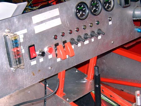
While doing all this I've been designing the gear linkage stuff and I've mostly got this sorted now. I've even done things like buying an M6 left hand tap in order to tap something to connect directly to the standard Honda gear actuator. As part of this, I've been thinking about a gear indicator as the one I've got is so useless. One of the reasons it's useless is, I think, because the signal from the speed sensor is poor. This is also connected to the DL1 and these are a series of frequency data (in Hz) from this sensor, taken at intervals of 0.01 seconds:
1815.43
2487.56
2043.60
5692.60
1573.15
1226.99
919.82
726.39
2612.10
1308.04
6382.98
1358.70
1559.25
As you can see the variations are just huge. I need to find out why this is the case.
In fact, as this data is going into the DL1 I'm currently thinking that the way to do a gear indicator is to take the data that the DL1 pushes out of the serial port and use that to calculate the current gear. If nothing else I could use the GPS speed data to calculate gear but that's probably a worse idea than using the engine's speed sensor as that latter is bound to reflect more immediately what's going on and should also work even if the wheels are spinning like mad.
Luckily, I've got the format for the DL1's serial data somewhere.
 It's taken me ages to get this far, but there's nothing really to talk about here. I cleaned
up the pedal box with an angle-grinder mounted flapwheel and then used a lot of masking tape and newspaper to mask
everything. I then sprayed everything with about 4 coats of smooth Hammerite, the colour of which seems to match
the chassis powder coat very closely.
It's taken me ages to get this far, but there's nothing really to talk about here. I cleaned
up the pedal box with an angle-grinder mounted flapwheel and then used a lot of masking tape and newspaper to mask
everything. I then sprayed everything with about 4 coats of smooth Hammerite, the colour of which seems to match
the chassis powder coat very closely.
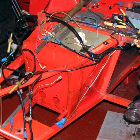
Since then, I've started to tidy up the wiring and the rear brake line as seen in the photo here. Before I go much further, though, I'll climb into the car (easier said than done bearing in mind the size of the new axle stands) and shove hard on the end of the pedal box. I know from the machines in the gym that I can manage about a quarter of a tonne of shove (sounds better than 250kg!) so that should do a rather unscientific test that the thing is going to stay in one piece.
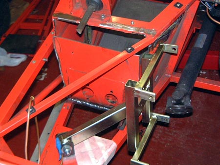
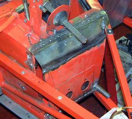
 With that well on the way, I want to get the engine in soon. If nothing else
that'll mean I stop tripping over it. I want to tidy up the transmission tunnel a bit and part of that is tarting
up the propshaft centre bearing support
slightly. When I made this before I didn't bother painting it as time was rather of the essence. I wanted to paint
it and, also, weld in another captive nut as I had had to fit it slightly differently from the way I originally
imagined I was going to do. Also, at some point a while ago I raised the bearing slightly by putting in a couple
washers. I wanted to make this permanent by welding these washers in position so they aren't so difficult to fit.
With that well on the way, I want to get the engine in soon. If nothing else
that'll mean I stop tripping over it. I want to tidy up the transmission tunnel a bit and part of that is tarting
up the propshaft centre bearing support
slightly. When I made this before I didn't bother painting it as time was rather of the essence. I wanted to paint
it and, also, weld in another captive nut as I had had to fit it slightly differently from the way I originally
imagined I was going to do. Also, at some point a while ago I raised the bearing slightly by putting in a couple
washers. I wanted to make this permanent by welding these washers in position so they aren't so difficult to fit.
The end result is shown here and is rather cleaner and tidier than it was. While I was at it I took out the reversing unit and cleaned up and painted the mounting brackets for that too. Unfortunately, I'd run out of red Hammerite and had to use silver.
 I've been thinking a bit more about this issue about using the DL1 to generate
dash information, in particular a gear indicator but the same approach would work for lots of other things. It
seems a sensible thing to do and I've spent a while pouring over the serial data format. I've now just about figured
out what's going on and worked out the algorithm needed to track the data changes. As part of this is would seem
sensible to mount the DL1 in a slightly more accessible position. The obvious place in above the tunnel just below
the dash. I'll need to make up some sort of special bracket and also relocate the in-cockpit fire extinguisher
release. The only problem is that the bracket will have to be very well fixed (as the DL1 is measuring acceleration
letting it vibrate all over the place is probably not that clever) and it needs to be absolutely horizontal. However,
no big deal really.
I've been thinking a bit more about this issue about using the DL1 to generate
dash information, in particular a gear indicator but the same approach would work for lots of other things. It
seems a sensible thing to do and I've spent a while pouring over the serial data format. I've now just about figured
out what's going on and worked out the algorithm needed to track the data changes. As part of this is would seem
sensible to mount the DL1 in a slightly more accessible position. The obvious place in above the tunnel just below
the dash. I'll need to make up some sort of special bracket and also relocate the in-cockpit fire extinguisher
release. The only problem is that the bracket will have to be very well fixed (as the DL1 is measuring acceleration
letting it vibrate all over the place is probably not that clever) and it needs to be absolutely horizontal. However,
no big deal really.
It'll also be a bit easier to reach the buttons and see the display on the DL1 when it's in this position.