 I’ve pressing on with the engine/gearbox mountings. Well, “pressing” is clearly a metaphor for something rather different. However, I have made some progress.
First of all, I’ve changed my mind how to do the diff mounting, as I realised that the original idea wasn’t going to work very well when it came to changing the sprockets and chain. I also realised that I hadn’t shown you a photo of the diff itself which I bought a considerable time ago. Here it is, along with the bearings that it runs in (which are just pressed onto the outside of the diff outputs).
This all has to be mounted in the chassis somehow in such a way that:
- You can get at things to connect the chain links together, and disconnect them.
- You can get at the diff to dismount and mount the sprockets.
- The tension in the chain can be adjusted.
- The driveshafts are pretty much straight(ish)
- The chain is as long as possible so as to keep it coolish.
- Nothing bashes into the chassis.
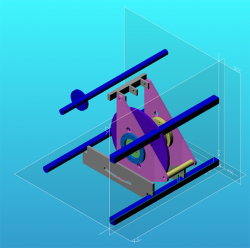
 This little CAD model here is where I’ve ended up, differently from the previous version. Essentially the diff is retained in a couple of triangular plates, that I’ll have to get laser/water jet cut. These swing off a top mounting that’s connected to the engine mounts, the two horizontal blue round things are parts of the engine mounts. At the bottom there’s another couple of laser cut plates with a curved slot that will do for clamping the diff in position. What I’ll probably do is use a turnbuckle for initial adjustment and then just use these things for clamping the diff.
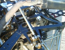
 To be honest, all of this is pretty much a copy of what appears on the back of several other cars. This is the back of another car, I think it was a Radical, that I photographed at Silverstone. There’s lots of bits here but you can see the driven sprocket and the aluminium plates that the diff bearings are mounting in. In this design the plates are oval shaped and are swinging from a top mounting point. Underneath there’s a couple of turnbuckles for tensioning the chain. To be honest I could replace those places with the curved slot in with two turnbuckles, one for each side. For some reason, though, I like the plates. I could well change my mind though.
Eagle eyed readers will have noted, though, that the CAD model above singularly fails to address requirement 6 above in that the driven sprocket goes straight through the upper rear cross member of the chassis. As I think I’ve said (I’m getting old, my memory’s failing) I will have to cut this weld in some extra supports.
Actually, I noted today that the new bottle of welding gas I bought a while ago is down to about half full. I’ve obviously been doing a lot more welding that I usually do because the last bottle lasted about three years; I paid far more to BOC for the bottle rental than I did for the gas itself.
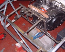
 So, after using that gas for a while longer I’ve ended up with the mountings looking like this photo. Notice that sitting on top of the engine are those two tools essential to people welding chassis: a wire brush and side cutters. 🙂
I spent some considerable time wondering whether the mountings should connect to the rear of the chassis; you could argue that all the diff/chain loadings are best handled by just hanging things off the engine. However, I decided that if nothing else the engine bay on the car is a socking great empty hole and it really needs some additional members to stop the whole thing flexing all the time. In fact, I may well add a bit more triangulation to these rearwards facing members. I ought to also see if I can get the mountings off, I’m always worried that as I’m fabricating all this in situ I might get to a state where I can’t actually take it to bits.
Next thing is to cut the mountings apart again so as to mount the reverser! I also want to mock up some diff mountings, perhaps using some plywood plates, to check that the chain run is acceptable. It’d be very annoying to get some nice aluminium plates cut only to discover that nothing fits properly!

Given that the four main engine mounts have metalastic bushes, shouldn’t the rearward stays onto the rear chassis member also have bushes in them? Or is the mix of bushed and non-bushed mounting points all part of a cunning plan too cunning for me to work out? 😉
I actually argued myself into this. I might well change it at some point as I no longer understand why I did it either…
🙂