Another small update of bits and pie ces this time. I’m at that bit of the build where there’s a whole stack of things to do and I seem to be spending too much time deciding what to do next.
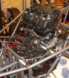
Anyway, here’s an airbox. I’ve decided to just start with the standard airbox. As I’d twizzled the one on the J15 around it wasn’t going to be possible to use that so I found another one on eBay and here it is…
 There’s actually loads of things to do. For example I’ve started putting some fluid in the braking system, and mopping up the mess that arises from leaving unions loose. I’ve decided to use some expensive high temperature fluid which should help avoid any horrors from boiling fluid. The problem is, it’s horribly expensive which make any leaks all the more annoying.
Back to the airbox which I’ve now fitted, doubtless temporarily, to the engine.  Having the secondary injectors in the right place means I can now start refitting the wiring and here’s the engine with the airbox and engine loom sort of in place. The loom was extensively hacked around for use on the J15 and as such I’ll have to put things like the ECU in much the same position as on that car. At least I will if I want to avoid extensive faffing with wiring.
I did in fact spend some considerable time deciding where mount the ECU and associated gubbins. One reason for this is that I’m trying to avoid drilling any holes in the chassis. (I’m sure this is going to fall  into the wayside at some point.) Eventually, I managed to work out a way of reusing the similar panel without actually drilling any more holes. Andy and Nick would be proud of me! The one extra-engine gadget that isn’t on here is the EGCV which, as before, I’ll tiewrap to the chassis somewhere.
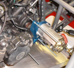
In other news I got the gubbins from Andy a while ago for mounting the reverse motor on the side of the engine. This was a couple of bits of laser cut aluminium and it took ages to work out how they went onto the engine, but  here’s the end result. Those bits of studding are just there to work out the optimal position for the motor. Once I’ve got this sorted I’ll make some spacers of exactly the right length.
One problem with this device is that it makes using the standard water pump impossible. Andy’s always been of the view that the pump should be replaced by an electric pump, although my view has always been that that’s just another failure mode. However, it seems as though I’m going to have to cave in this time…
Finally, as part of the electics thread I’ve been thinking about where to put the switch panel. The original plan was to try and reuse the panel from the J15. However,

I’ve decided that it’s just too grubby so I’m going to have to start chopping up aluminium and somehow working out where to put that aluminium. Current favourite is somewhere under the forward roll bar, as you can see in the photo. Problem is, how to avoid the dreaded holes in the chassis, especially on the roll hoop… I wonder how well it’d fit using just tie-wraps?

To attach firmly to a tube without drilling holes, I use Cushion clamps (adel clamps, p-clamps, lots of names). Any with a metal strap and a rubber cushion will grip well but have a look on evil bay for MS21919WDGX (where X is the diameter in 1/16ths) they are the mil-spec version.
Here is an example (hope the link works) – it’s for an anlge but you get the idea…
Hi Tim, you could try Adel Clamps a used in aircraft. Here is a link to
an example of what I think may work for you. http://home.hiwaay.net/~sbuc/legaleagleXL/firewall-forward.htm
Richard