
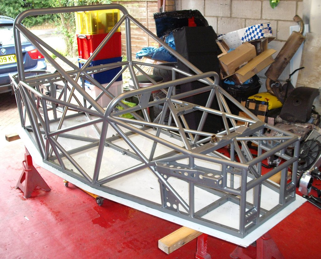
 So, after a couple of weeks, I got the chassis back and put it up on stands in the garage although, as you can see, there’s rather of lot of junk in the garage as well.
The floor of the chassis has been bonded in, as well as riveted with some rather natty flush rivets. Now, all I’ve got to do is to put it together. The only problem at the moment is that the grey semi-shiny finish seems to upset the camera I use and quite a lot of the photos look bizarre…
 For example, the first thing I did was to put the steering system in. Here it is, assembled in chassis that appears to have gone sort of stripey. Oh well. The steering rack is inserted in the chassis here, the upper steering column—and and old wheel—is fitted and between the two is the rest of the column. As you might be able to tell I’ve painted this bit white; I wasn’t sure whether powder coating it was a good idea as the welded on UJs include bearings that don’t seem to be a good idea to put in a powder coating oven. If you’re paying attention to these very occasional posts you’ll remember the photo of the welded and pinned column from a while ago.
 Next up was to put all the suspension units in place. The next photo shows the rear ones. One issue here is that I’m trying to reuse the dampers from the J15. These are 2.25″ units rather than the 1.9″ ones that Andy uses. This means that a couple of things have had to be slightly modified to clear the larger units. If you look very hard at this photo you can see where I’ve had to grind a small amount of aluminium away from the rear damper mount clevises to clear the damper body.
One problem with the rear suspension is that I took ages trying to fit the rear ARB which just didn’t seem to reach to the right place. After an age I finally phoned Andy and it  seems that he’s supplied the part for the older Sabre chassis which is about 100mm shorter. He’s getting a new one for me…
This next photo is the front suspension. This time the ARB is attached and you can also see the pedals in the chassis and the fluid reservoirs on the front of the chassis. The fluid reservoirs were actually bought originally for the J15 but I used something different in the end. My waste-not policy, otherwise known as let’s fill the garage with crap, wins out again.
One issue that I did have with the suspension is that I had to trim quite a few of the top hats provided by Andy. One issue was that my dampers have the eye in the damper mounted off-centre and although Andy’s tophats fitted, one of them was entirely shrouded by the damper body. I also had to trim a few to get proper articulation of the suspension, for example the ones that connect to the ARB drop links in the earlier photo. 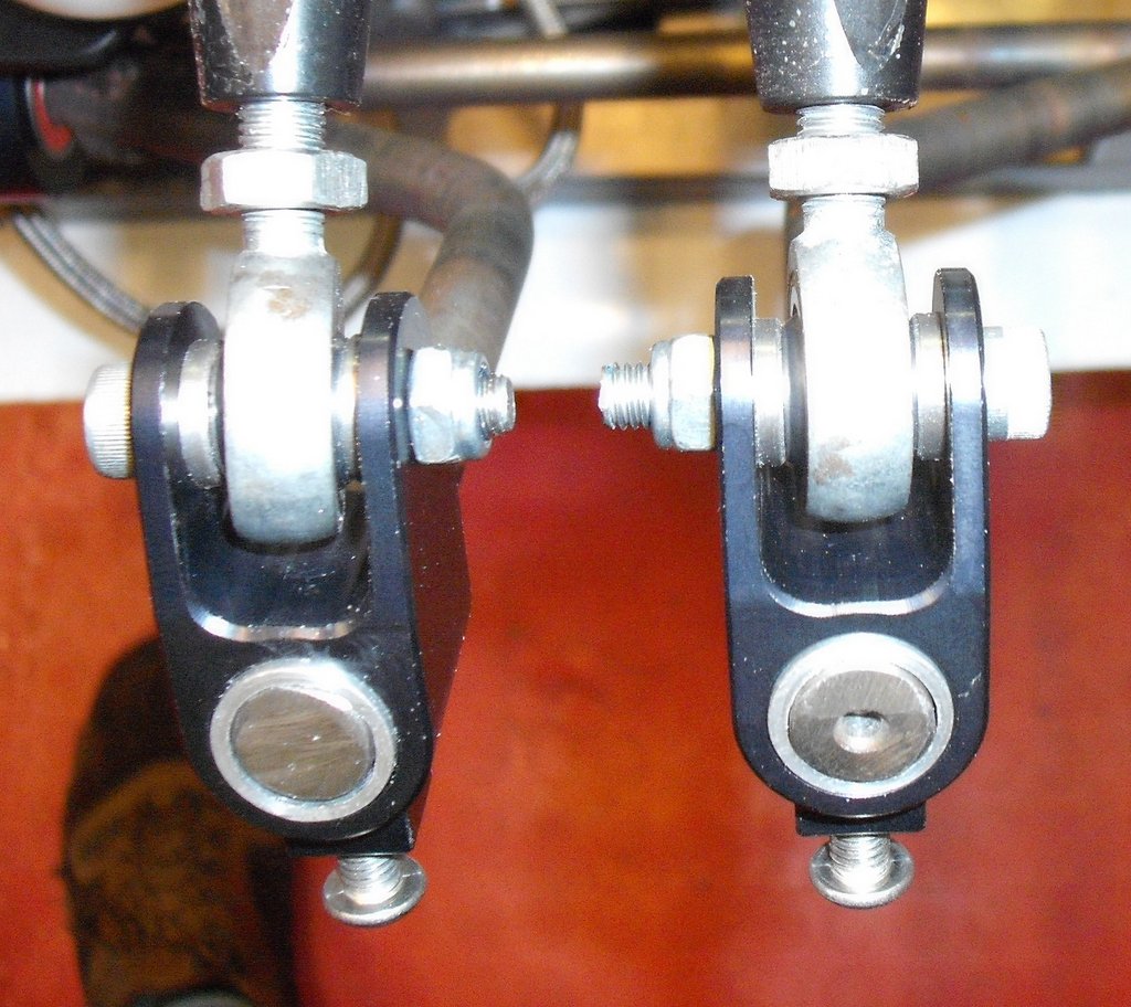 Finally, the ones in the ARB sliders, as in the next photo, had to be trimmed just to get the rod ends into the sliders. (I wonder if the rod ends I’ve got, which again were inherited from the J15, are the wrong dimensions somehow?) In this latest photo, you can just about see the sleeves that I machined to connect the 1/2″ ARB to the 5/8″ ARB sliders. This is deliberate as it allows for thicker ARBs to be fitted.
The next step was a bit on the momentous side. I decided that the time had come to start fitting the engine. One of my concerns here was making sure that I could get access to the oil drain hole one the engine was fitted. I asked Andy how he fitted it and, on his advice, rotated the lower part of the sump so that the drain hole faced towards the rear right  corner of the car. I then fitted the engine into the car, aided by the trusty engine hoist that I bought ages and ages ago after I got fed up renting one all the time. It’s more than paid for itself over the years, probably ten times over.
In this photo the engine is half in. I’ve got the front mounts attached and am lifting up the rear of the engine so as to rotate it slightly and make a bit more space under the oil drain. (Note the also ancient bit poly-propylene rope that I must have put on here when I bought the hoist.)
And, 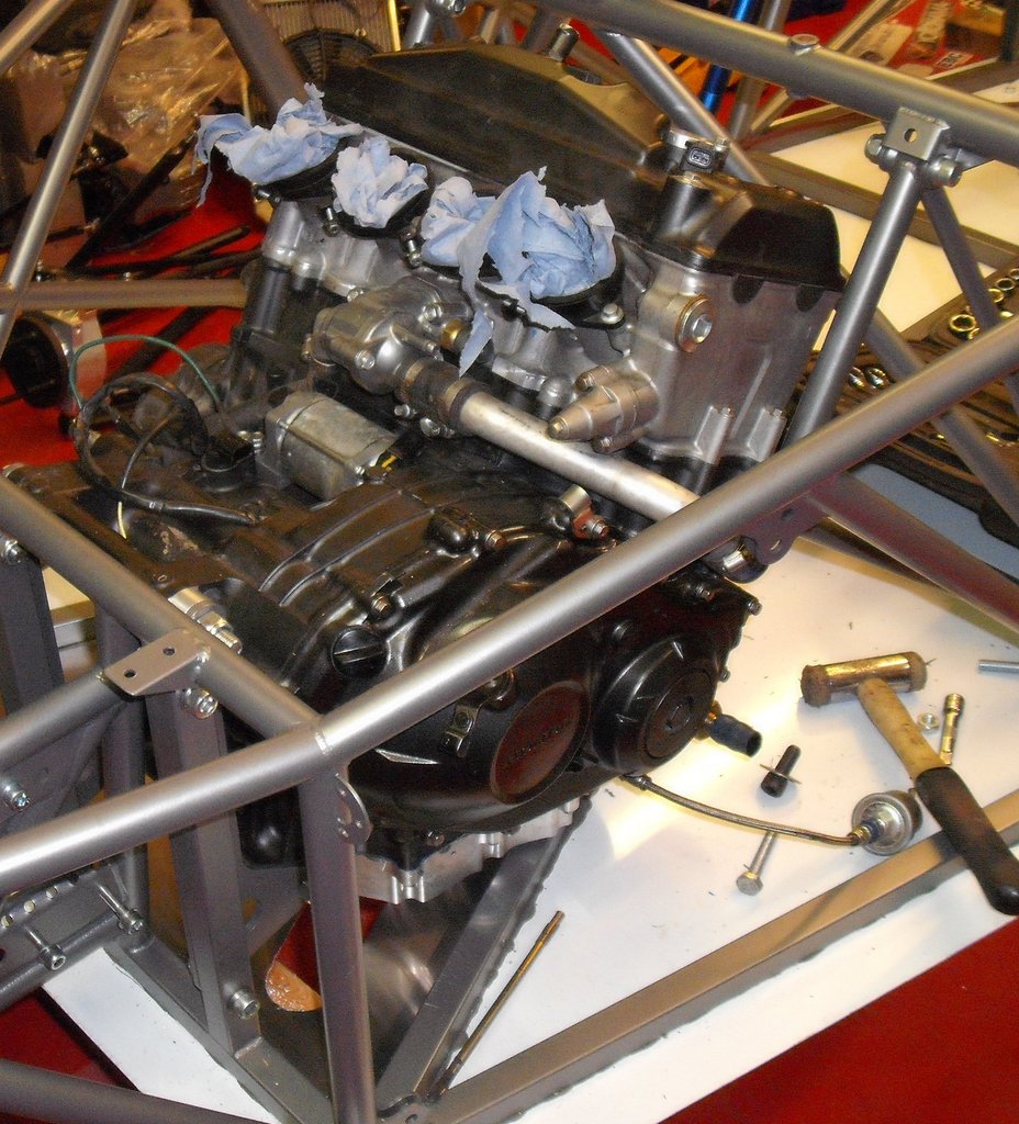 here’s the engine in the chassis. If you look really hard you can see the hole in the floor for draining the oil out; you can see the red floor peeping through. One of the nice things about this stage was that Andy’s engine mounts fitted exactly. They just needed a little bit of help from that soft-headed adjuster you can see in the photo.
Next thing was the gearchange and this has taken me some time to make it work right. If you remember, it’s made with a short push-pull cable with a transverse shaft behind the engine and behind the steering wheel to rotate the actuation onto the end of that cable.
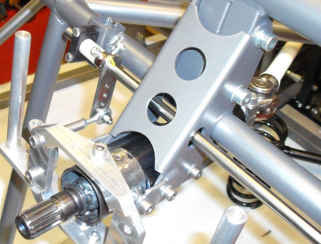 Here’s the front shaft, well one end of it. One real issue I’ve had with all this is making the cranks sit properly on the shaft. I’ve made the shafts with some snazzy bearing rods made of a ferritic stainless steel (I can tell, because magnets stick to it). The problem is, it’s really hard which means the shaft’s don’t bend but it also means making a connection by, essentially, friction doesn’t work too well. Hence the rather ugly M5 cap head bolts that you can see attaching the crank to the shaft. To be honest, this is offending me and I might see if I can drill and pin the crank onto the shaft now I’ve got everything in the right place. The problem with doing that is actually managing to drill a hole in the shaft. It’s pretty much impossible to cut with a hacksaw for example so drilling it might be a complete joke…
 Here’s the transfer shaft at the back of the engine, featuring the same crank attachments. To be honest, they might look ugly but they do seem to work nicely. There seems to be essentially no play in the gear change and it’s all nicely adjustable for rate due to all those cranks and holes.
And finally, for this update, I fitted the clutch cable. I had to made a little adapter to  connect the cable outer to the chassis hard point just behind the clutch pedal, as in the photo, but it fits nicely and, as it’s exactly the same sort of cable as I had on the J15, I’m pretty sure that it will work well. I don’t think that cable’s going to interfere with my feet. If it does I’ll make some sort of cover for it out of aluminium
Good to see some progress – the powder coating looks good.
How about grub screws instead of the cap heads?
Tried that, in fact it’s what I did first. They don’t grip well enough; the material is batsrad hard…
Tim
Well done Tim. Starting to come together. I’m looking forward to you moving up the results again 🙂