 Well, at least I can now get back to the Spektre! As I think I’ve said a few thousand times I need to get the engine mountings done. If you’ve got a long memory you will remember that I did the one at the top right of the engine and it was time to press on with some similar things.
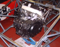
So, here’s the engine with the top left one done as well. This means that the engine is now happy to swing, it’s easily pleased, from these two top mounts. Consequently, I’ve now taken away the  arrangement of blocks, aluminium shims and lumps of wood that as balancing the engine in exactly the right (ish) place and replaced it with a scissor jack as in the next photo.
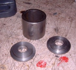
By the way, if you look closely at the photos, you can see that the mountings appear to be made using metalastic bushes. The intention is that this will eventually be the case. However, while I’m welding to the sleeves into which I’ll press the bushes I’ve made up some little “top hat” mountings as in the photo here.
 These fit either side of that large tube and locate it properly for the 1/2″ bolt that will eventually go through the bush but locate is so that I can weld to the housing without messily melting the rubber in the metalastic bush.
The next part of the mounting is to do something similar for the rear mountings of the engine. Jeremy uses a sort of large cradle that goes under the engine but I’d prefer to get the engine as low as possible in the chassis. Hence, I’ll just have a mounting at the rear of the engine, although I’ll need to use both the top and bottom rear mountings so as to control the torque reaction of the engine as I plant my foot firmly on the loud pedal and spin off into the scenery.
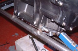
 The first part of such a rear mounting is a tube going widthways across the chassis and bolted to the lower engine mounts. Here’s the start of it in this photo.
This is made from a lump of 1″ tubing and to which I’ve welded (quite neatly, I think!) a couple of tabs made from 5mm steel which locate on the engine rearmost mountings. It’s all retained with a long 12mm bolt.
The intention is to connect this tubing to get more metalastic bushes mounted to the lower side members of the chassis. I’ll then make more of a frame up the back of the engine to stop it rotating about this initial tube.
At that point, I’d hope to have the steel for the roll cage which is still “in the process of arriving” so I’ll be able to make the cage and then, finally, I’ll be able to get the chassis powder coated.
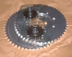
 Apart, that is, from the diff mounting which I’m still thinking about. As part of refining this I’ve bought some sprockets from B&C Express. The photo here is of two drive sprockets with 14 and 15 teeth and two driven sprockets with 50 and 52 teeth. This will allow me to make effective diff ratios. This compares with the 3.21 that the Fury has. The difference, though, is that I’m intending to use 205 section rear tyres with the Spektre now I don’t have to worry about having a fixed diff ratio.
The intention is to saw these driven sprockets in two so as to make them easy to change, I’m assured by B&C Express that it’s OK to just use a hacksaw! The one thing that I’m concerned about with this is that the sprockets are mounted to the diff using 8 mounting holes. Two of these are fitted with 14mm retaining dowels which fit exactly which is nice. The other holes, in the diff anyway, are 27/64″. (I’m not making this up.) This means that a 10mm bolt fits with a clearance of about 0.75mm which seems rather a lot to me, especially once you remember that once the sprocket is cut in two it’ll only have one alignment dowel per half. I might have to make some little sleeves for 10mm bolts that’ll fit exactly. Problem is, the wall thickness will be a mere 0.35mm which might be a mite tricky to machine. I suppose I’ll just have to go dead slowly…
As well as buying these sprockets, I also bought a chain and the world’s most expensive tool for splitting/making the chain links. (Think £100 for a sort of hand-held press.) It’d better work well…

great to see more progress on the car, have the lawyers decided what it’s called yet?
as for your sprocket problem could you bolt them both together on to the diff. Then drill two more dowel holes before cutting in half.
great idea on the metalastic bushes. think i may pinch the idea for repairing the suspension mounts on my mgb!
gav
I did wonder about drilling more dowel holes. The problem is, I don’t really want to drill bigger holes in the diff flange itself; mainly because I’m worried that something would go horribly wrong! 🙂
As for the bushes, it is a great idea but, to be completely fair, I pinched it from Andy Bates! 🙂
Tim
well thanks to andy!
Don’t think you have put a picture of the diff on here, so not entirely sure of the layout. But all the same, not sure what could go wrong. if you use a pillar drill with the diff well clamped, so nothing can become miss alingned. or maybe you could make a spacer with dowels in this could also be used as a template if you need to make more sprockets in the future. and if you have one either side of the sprocket like a sandwich it would put back some stiffnes. of course this may affect alingment of things, meaning you have to remount the engine!
gav
Actually, I suspect that it isn’t a problem after all. The reason is that the big hole in the middle of the sprocket is a pretty close fit on the diff anyway. That is, even just just the single dowel it probably won’t rotate around that dowel because to do so would required the half sprocket to move into the diff itself.
If that doesn’t pan our, Gordon’s suggestion of using a smaller bolt is a pretty sensible idea. I’ve also realised, rather retrospectively, that a 7/16″ bolt would be a pretty good fit in the diff with just 1/64″ slack. I suppose the sensible thing to do would be to find some of those super high quality US airforce surplus bolts that I’m told are out there…
Tim
How about using an M8 bolt for 2 of the mount points, allowing you to run the bolts through sleeves/dowels with 1.35mm wall thickness? M8 will I’m sure be more than adequate in conjunction with the M10s. This assumes that you’re using bolts and nylocks, not tapped holes in the diff.