As I did for the Westfield, this page is intended to document anything that isn't obvious from the build manual. There's probably rather a lot of these, as the Rush build manual is much less explicit than the Westfield one. This is no bad thing, especially as the Rush one has rather more real drawings in it. However, in some cases there's little or no information there.
If anyone else has any suggestions mail them to me and I'll include them here, subject to the obvious caveats.
Duncan's Dax build page also has a lots of tips on it.
The Westfield tips should also be read, for the general purpose things.
Here's a small index:
- De dion tube
 It
isn't clear from the manual what order to install this in. After rather a lot of experimentation, it's:
- Install rubber bushes for diff in chassis.
- Install De Dion A frame balljoint in chassis.
- Install diff.
- Install bushes in A frame
- Install A frame
- Install De Dion tube and connect to A frame.
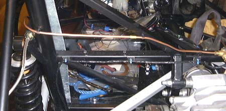
- Rear brake lines
 With a de Dion rear axle it's important the fit the brake pipes in the way shown in the
photos. If this isn't done then the flexible pipe is in danger of snagging in the rear
wheel.
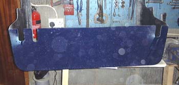
- Rear tub
 If you have a de Dion chassis, make sure to cut some additional slots for the chassis members
under the tank and don't cut out the clearance for the springs that are not on the de Dion chassis...
The manual is rather confusing about which measurement to use for fitting the rear tub. From measurement of cars in the Dax showroom, the best measurement to use is the one that's in the manual chapter on fitting the rear wings. This recommends a distance of 410mm between inside of the boot box fitting and the top of the chassis rail that's beneath the roll-over bar. See the build diary for more details.
- Wheel studs
- If you are fitting snazzy alloys to old Sierra hubs you may well find that the studs are not long enough. The studs are 12mm in diameter and you need at least 12mm of thread in contact with the wheel nut. If you don't get this you can change the studs quite easily by whacking out the old ones with a big hammer and bashing a new stud in with the aforesaid implement. I always put an old wheel nut on the end of the old stud when knocking it out to avoid bashing up the threads too much.
 Speedo sensor
- Most V8 Rush builders seem to use the mechanical speedo drive that comes naturally out of the Rover gearboxes. I've never understood this as you need a socking great cable going around the car, and that cable is rather tricky to fit in the cabin as the outlet from the gearbox points in the wrong direction. Much better, I reckon, to use either one of the electrical adapters that fits into the mechanical takeoff on the gearbox, or an aftermarket sensor. There are several varieties of aftermarket sensor, the Greengauges website lists several of them. I've used a reed switch one as that's the one that Greengauges seem to think is the easiest. However, make sure that you mount the sensor on a non ferromagnetic mounting, such as an aluminium bracket, as it doesn't seem to like working on a steel one.
 However, after writing the bit above I eventually lost faith in the reed switch
sensor anyway. The reason for this is that it is just about impossible to get the reed switch close enough to the
magnets. I found that it needed to be < 0.5mm away and with the compliance of the various mounting bits this
meant that eventually the magnets bashed the sensor and fell away from the prop shaft. I converted to using a proximity
sensor mounted on a bracket and pointing at the heads of the lobro joint bolts. This still has to be pretty close
to the bolts, but isn't in danger of knocking them off.
 Bracketry
- It seems to be necessary to fabricate loads of brackets for the Rush, as most things are left up to the builder
to decide what things are and where they should be put. I ended up making all sorts of bits out of steel and aluminium.
In cases these are bolted on and in other cases they are welded on, such as the one here for the coil
and ballast resistor. It must be a better idea to think about this in advance rather than in the piecemeal way
I did..
It's probably also a good idea to raid the offcuts bin in your local metals supplier for various chunks that you know are going to come in useful.
 Fan
Fan- If you have a Rover V8 then the cooling is marginal. So, just get the biggest fan you can get, not the sort
of weedy one I did at first!
Having eventually found that I was having trouble getting the airlocks out of the cooling system it may well have been that this small fance would have worked. All the same, getting a big one seems sensible.
 Safety
- Sorry to lecture you, but take care about safety in the garage. A particular fetish of mine is looking after
my ears, which are a bit dodgy probably as a result of a lot of DJing back in the 70s. Looking after bits of the
body also extends to my lungs and eyes, hence all this safety kit hanging up in the garage. All this means that
when I'm using an angle grinder in earnest, with eye and ear defenders, I must look a bit daft.
As well as the personal protection things, make sure you've got a fire extinguisher to hand, especially if you're doing things like welding.
 Measurements
- There tend to be lots of occasions when accurate measurements are needed. I strongly advise investing in at
least a vernier caliper, it will be worth its weight in gold. What's more, you can get perfectly serviceable ones
for next to nothing these days. This combined caliper and micrometer set cost me about £20.
Anyway, a vernier caliper is a truly clever idea, and you should get one just because of that!
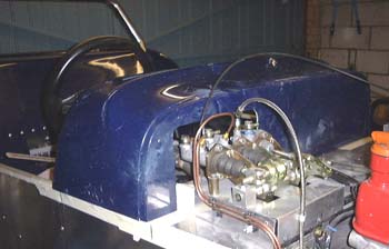
- Side panels
- I found fitting the side panels was horrendously difficult. In my case this was due to the thickness of the lowered floor trying to force the panels too low. I eventually fixed this by cutting most of the rounded part of the top of the side panel off, relying on it being covered with the stainless kick strips. All the same, it still didn't fit right and I had to mount the scuttle on some spacers to fill up the space between the flange on the top of the side panel and the chassis.

 Make sure that you check the position of the scuttle with all the bodywork in position.
For me the scuttle was too wide for the "obvious" position of the bodywork sides and was too far back.
 If you get a kit from Dax, when you pick it up give the wishbones straight back
to them, along with the lower balljoints, and get them to press them in for you. Unless you have a hydraulic press,
you're not going to be able to do it yourself.