 I’ve been pressing on with the Spectre, albeit not making real progress although perhaps laying the basis for real progress. As I said last time I’ve been measuring up where to put the engine. Oddly, the big issue here seems to be access to the spark plugs and coils; everything else doesn’t seem to be much of a problem.
I think I’ve come to the conclusion that getting the engine as far forward as possible is actually more important than being able to easily access the spark plugs. I used to drive a Subaru Impreza. These have a fantastic flat four engine, I never was able to work out how they got access to the plugs in that, it must have been through the wheel arches because you certainly couldn’t reach from inside the engine compartment! I think for the Spectre I might have to make some access panels so as to get access from inside the passenger compartment. Even then it’s going to be difficult though and it might be necessary to slacken the engine mounts to shift the engine slightly.
The main reason for looking so hard at the engine position is to work out where to put the diff and the measurements I’ve made have enabled me to made a fairly comprehensive CAD model of how I want to mount the diff. One view of this is in the diagram above. The blue bits are the engine itself and various bits of the chassis, the rest is stuff that I’ve come up with. I think I’ve ended up with something that’s strong enough and adjustable in the right way. I’m going to have to get some expensive plates laser cut in an expensive aluminium alloy though.
By the way, I’ve decided to try and record lots of detail here because there’s not exactly a build manual for a Spectre so this might form some sort of useful service (!). So, forgive me if I bang on rather a lot, and probably in a badly edited manner.
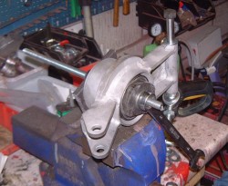
 The rear wheel bearings were pulled into the uprights using a collection of steel plates and a long piece of M12 studding. (This was cheap stuff, made out of cheese, and frequently succumbed to my ministrations so I had to angle grind it off a few times!) However it did work and I fitted the circlips that are provided in the boxes that contain the Ford bearings. (They’re actually SKF bearings which is nice and comforting as they seem to be excellent products.)
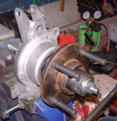
With the bearings in position the next thing was to pull the hubs into position, along with some rather long wheel studs that I fitted a while ago. Luckily I had these in stock and didn’t have to go to the local barry boys’ outlet in order to buy some new ones. I always feel faintly dirty after going there.  I pulled in the hubs using that same piece of M12 studding and the eternal standby when one needs a round dolly, a couple of large sockets.
The problem that I haven’t solved with these uprights yet is what brakes to get for them. I could probably use the Powerlite handbrake calipers that I use on the Fury. The (slight) problem with these is that I don’t know if I can get some mounting blocks for them. It’s not a big deal to machine them but even then I don’t know what discs to get. I’ll have to phone Rally Design and talk to them about it. It’d be nice to use the non-handbrake calipers as I could use larger discs then which could well help with the car, I’m assuming that the mid-engined aspect will allow me to use more rear braking than I can with the Fury. One possibility is to use some sort of transmission brake for the handbrake meaning that I could use non-handbrake calipers. Or, of course, I could use the Sierra calipers but I’m congenitally incapable of that. They all need, in my opinion, to be subjected to the float test that Carroll Smith recommends for old springs. That is, you lob them in the nearest pond and you’re allowed to use all the springs that float. That sounds like the proper test for the Sierra handbrake calipers to me.
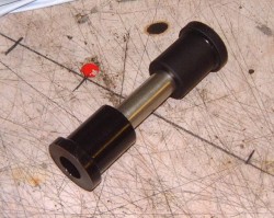
I then turned to thinking about the suspension. I decided a while ago to do this very carefully and slowly. As I mentioned I’ve been looking again at using PU bushes instead of the rubber ones that Jeremy provides. The next photo is of one of these which I’ve been pressing into service. Now I’ve got a lathe it’s actually a lot easier to fit these things as they polyurethane can actually be  machined slightly so that things fit well.
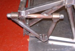
I started doing this, but to be honest I struck some problems pretty quickly. The first one is that the rear upper wishbone is mounted in a slightly odd manner in that the bushes fit either side of a tube that’s welded into the chassis. The problem is that the PU bushes are really designed to locate in U shaped brackets in the chassis and the bracket itself acts as a support for the outer wall of the bush (as at the bottom left of the photo). This doesn’t really fit with the rear upper wishbone mounting so I reluctantly pressed two of the rubber bushes into one of those wishbones, and promply got copper slip all over my overalls which is a bit of a bummer. (What is it about copper slip in that it sort of migrates around the place without you being aware of how it’s doing it?)
 I then struck the next problem, which is well-known foible of Jeremy’s. This is that he’s provided 12mm bolts that go through the bushes and, in this case, the tube in the chassis. Eagle thoughted readers will have noticed that the bushes, being ancient British ones, are in fact ½” ID, meaning that there’s 0.7mm of slop when you put and M12 bolt in there. Jeremy’s point of view, as I understand it, is that the bolt is just a clamping device that holds the bush in position, the bush doesn’t pivot on the bolt. That is, the bolt doesn’t locate the bush so that 0.7mm is irrelevant.
My view is that’s only a partial truth. The bolt does indeed locate the bush up and until it’s torqued down. What’s more, that can’t be done until the car’s on the ground because you need to make sure that the rubber doesn’t “wind up” until the suspension’s in the right place. That means that that 0.7mm is slop in the position of the suspension pickup points. What’s more, frankly, it’s nasty and rattles until it’s put together.
Still, it’s easily fixed. In the case of the rear upper wishbone the tube in the chassis is actually ½” ID too so a ½” bolt did the job fine in anycase. In fact, the photo has a lump of ½” UNF studding in there as I had some left over. However, I’ll try and find a nice long bolt instead. Interestingly, the bolt that Jeremy provides at the bottom pivot for the rear upright is a ½” one. In that case, though, it’s locating a rod end so I think I can guess what his argument is going to be.
This is all a load of woffle really, that obscures the fact that I’m still not happy with the PU bushes. In fact, I think I’ll put the suspension together with Jeremy’s bushes, although I’ll use ½” bolts and drill out the mounting brackets to take them properly. In the long run, though, I’m just not happy with these bits of rubber and so on. It makes sense to plan to make some new wishbones that can use rodends for pivots. Obviously, you wouldn’t want to do this on a road car, which is really what Jeremy is aiming at, as it bangs and crashes horribly. However, on a race car that’s what ear plugs are for.
I’ve also been thinking about pedal boxes and reverse mechanisms. I’ve not got a specific conclusion as yet though, I’ll write something here when I do though.

RE: Handbrake, What about using a cheapo cable operated bicycle disc brake mounted to the drive shaft???