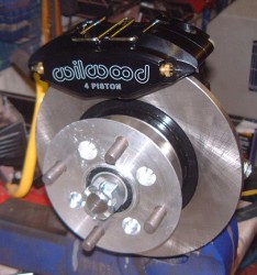
 I’ve finally got the front uprights through from Jeremy, who hadn’t received them from his suppliers for ages. Here’s a photo of one of them, as you can see it’s jolly shiny!
Oddly, I seem to have two discs too, which I didn’t realise that Jeremy was going to supply. They’re not the size that I’m going to use, and have already bought, but I might be able to press them into use as spares, I suppose.
 I’ve already bought some Wilwood calipers from Rally Design for the front brakes, which are exactly the same as the ones I’ve got on the Fury. I mounted on temporarily on the upright as you can see in this photo; you can probably see that this disc is actually rather smaller than the ones I want to use. They do seem to be the same offset though.
One odd thing about these uprights is the hub. In the centre of a hub you usually have a flange that fits snugly into the centre of the wheel. In fact, it’s often too snug as those of you who’ve had to take wheels off using a large mallet will testify.
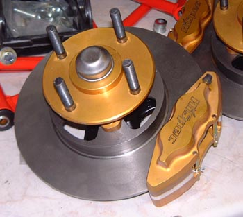
 The photo on the right here is the original Fury front upright with the HiSpec brakes that I eventually consigned to the bin. You can see the pronounced centre to the hub here, something that’s absent from the Spectre hub above.
Conventional wisdom is that it’s this flange that takes the radial load of the wheel flailing about, with the wheel studs just providing some axial tension. That seems to make sense. However, the Spectre hubs are those that are supplied to Caterham just like that, and friends with Caterhams have said that this is indeed what they’re like. So, perhaps they’re going to be fine? I’ll have to think about this a bit more.
I could, of course, find some other hubs to use. I did find another company who list Caterham alloy hubs and the photos on their web-site shows hubs with a much more obvious central flange.
Hmmm. Any suggestions?
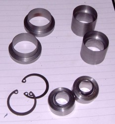
 In the meantime, I’ve finished making the parts for the spherical bearing mountings in the rear wishbones. Here’s the complete set of parts which is precious tiny considering the size of the lumps of steel I started out with. I test assembled one set, as below. At this point I did worry that the spherical bearings seem tiny, especially considering the humongous size of some of the rod-ends that Jeremy specifies. The bottom side of the front wishbone has a 5/8″ x 3/4″ rod end that connects it to the chassis which is, in my experience, vastly overrated for the application. The equivalent position on the Fury uses a 1/2″ x 5/8″ rod end without problem. Actually, I originally used a 1/2″ x 1/2″ but that did bend a bit under the braking loads.
So, I looked up, yet again, the spec for the spherical bearings. They are rated at an “Ultimate Static Radial Load” (that is, up and down in this application) of 19,875 lbs. I suspect that probably means lbf really. If so, call it 88kN. Clearly that’s fine for the static load which will be in the region of 300kg or about 3kN. However, the dynamic position is more complicated. I’m not an expert at this but from first principles if the unsprung weight is, say, 30kg, then 88kN would accelerate that mass through the full suspension travel of about 150mm in 10ms–completely ignoring minor issues of having to stop it again. As the usual suspension frequency is in the region of 1Hz that implies that the forces are rather lower than the 88kN mentioned about, by nearly two orders of magnitude. As such, that weeny spherical bearing should be OK.
Still seems tiny though.
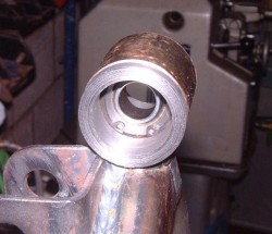
 I now need to actually put these into the wishbone. This will actually involve welding something to the wishbone, which is the point at which something could go horribly wrong. The photo on the right shows a set of these parts test assembled into the bearing housing on the wishbone. You should be able to see the circlip sitting in there which is retaining the spherical bearing in position.
The problem is that the bearing is a pretty snug fit in these sleeves that I’ve made. Actually, it’s very snug. If something distorts when I weld it in then I’ll never be able to get the bearing in and out, which is the whole reason I’ve gone to the faff of making all these bits. I guess if it all goes horribly wrong I can still go back to Plan A (or was it E?) and cut the whole thing off and weld a rod-end bush in so it isn’t the end of the world.
Watch this space…

Hi again Tim,
What about a structural adhesive rather than welding? No chance of distortion, and the thin film with a press fit would give a strong bond.
I agree with the comment about the Caterham hubs, I also prefer hub-centric wheel mounting, but I have seen stud-centric before so it’s definitely normal.
N.
I had wondered about an adhesive rather than welding it, but decided I didn’t know enough about it. Anyway, I’ve welded them together now, very slowly and very carefully, and it seems to be OK. Photos coming soon.
Thanks for the note about the hubs. Seems odd but I’m hoping it’s going to be OK!
T
Tim
I had the same problem regards wheel hib flanges. the biggest issue for me was holding the wheel in place when changing wheels. I made up some spigots to do the job. http://ctrdevelopments.com/Arachnid/2008/04/03/wheel-spigot/
Could you do something similar. Would save the expense of new hubs!
M
Hmm, there’s an interesting thought. TBH, I think I’ll leave it along for a while, I don’t think locating the wheel when changing will be a big issue, although time will tell.
T
Tim
Where did you get the uprights?
I am looking for a similar upright that uses a sherical bearing rather than a trunnion.
I’m in Canada.
Thanks
Thumper,
I got the uprights from Jeremy, that is from Sylva. (See the link on the right.) However, he gets them from the same people who sell the product to Caterham, although they might be a different geometry from the Caterham ones. They came originally from ESP Automotive Components of Coventry, their phone number is, in the UK, 02476 460000.
Hope that helps,
Tim