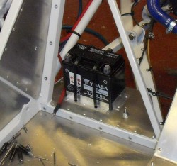
 It’s time to press on with the electrics, and the first part was to fit the battery. I decided to position this low down behind the driver’s seat so I made a little plinth for it and held it in place with some bits of aluminium angle and, yes folks, some chunky tie-wraps.
To be honest, with the seat back in position the battery is going to be harder to get at than I’d like. However, it’s nice and low here. It might be worth wiring in a charging socket somewhere to make the Optimate easier to connect.
 Best bit though, for a while, was that with the battery in I could connect it up and see if things started to work. After calming myself down I connected up a couple of the fuses and turned on some switches. And, some lights on the switch panel came on! Amazing…
Yes, I know the main beam warning light looks more like a search light than anything else. However, it works. The warning light for the logger (left column, penultimate row) looks a bit weedy though. I might have to change the switch.
So, flushed with enthusiasm I turned to the engine loom, easily the most complicated bit  of the wiring as, like all modern bike engines, the CBR1000RR07 has lots of sensors and other gubbins associated with it. So, as last time I started with a complete bike loom and proceeded to eviscerate it on the kitchen table. Here’s the end result, having made its way as far as the top of the kitchen hob.
What I did was really to remove all the wiring that I definitely don’t need, like that for the lights, the lean angle sensor, the stop relay and so on. I haven’t change the remaining wiring at all though, as I was hopeful that I could keep a good deal of the rest of it as standard.
This was predicated, though, on where I mounted the ECU which is the eventual source of most of those wires. The standard position is on top of the airbox which might be fine on the bike but would put it up in the air in the car and open to all sorts of objections from scrutineers. However, somewhere in that vicinity did seem like a nice idea as it would enable the existing wire lengths to work.
After some thought I decided mount a little aluminium plate on the back of the airbox, between it and the engine mounts.  You can see it in the photo. It’s mounted on little vibration-absorbing bobbins so hopefully the electronics won’t get shaken to pieces. This does mean, though, that I’ll have to earth the plate if I want to use it for connections.
I quite like this solution, especially because it helps to support the airbox as well, as experience has shown that scrutineers have a bad habit of leaning on the airbox and knocking it off its mounting rubbers.
The intention is to mount the ECU, the regulator/rectifier, the relays for the starter and reverser motors and the Power Commander on this plate. They should, just, fit!
One slight problem might be keeping all this clean in the onslaught of grot from the chain. I may have to make some sort of cover for it, or perhaps wrap it in a plastic bag. I’ll see how it goes.
Work is now progressing on fitting all the engine wiring. I’ve had to extend the wiring for the inlet temperatur e sensor and the secondary injectors. The standard ECU position is very close to those so that’s not surprising. However, I’m hopeful that most of the rest of the engine wiring can be accomplished without major modification to the remaining bits of the engine loom. There’s still a heck of a lot of wires though.
