 Phew! I have finished as much of the panelling that I’m doing at the moment, leaving the car looking like the photo here which, I’m sure you’ll agree is not one of my better photographic efforts. Still, it’s the best I could find without venturing back to the (bloody freezing) garage. All of the panels are there now, apart from the seat back and above the driver’s legs. The former’s not there because I want to retain easy access to the engine compartment and the latter because I need to finish the steering column first.
 The plan is actually to make the seat backs easily removable, as are the tunnel side and tops, so that it’s easy to get access to the engine’s exhaust side and things like the oil filter.
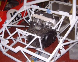
On the subject of the engine, that was the next topic. So, I inserted some metalastic bushes in the mountings, where previously I’d use the turned adapters I showed you, and bolted the upper mountings to the engine. As a matter of interest the bosses in the CBR1000 block are tapped for M12x1.25 which is pretty hard to find as it’s something like M12 superfine. However, a quick search on eBay turned up a supplier to sells a lot of such things; very useful.
With the upper mounts on the engine I hoisted the engine up and located it in the top mountings, just letting it swing there. I then chocked up the engine (it’s easy enough to move around by hand) and bolted the rear mount to it. In fact, being a bike engine it’s always easy to move around. With the upper mounts on I picked it up and carried it across the garage. Given that that’s 180bhp and a 6-speed sequential gearbox I can never understand why other kit car builders use things like K-series and Zetec engines as they’re fantastically heavy in comparison.
Anyway, I could then bolt down the rear mount. This was a slight struggle as the powder coating seemed to have changed the shape of the mounting very slightly. Or, more likely, exposed some of the stresses in the shape due to the heat of welding it.
All the same, the engine was now in. Symbolically, I’ve threadlocked, or nyloced, all these mountings which is an indication of the fact that I’m intending this to be it. Until I realise that I’ve made some awful error, or course.
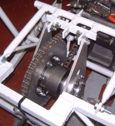
Next thing was to mount the diff. You will remember that I had a problem with the alignment of the split sprocket and took the diff carrier apart to see what I could work out. Using the other sprocket that I have bought I offered it up to the diff and it fit perfectly; meaning that it had been machined correctly. I then split that one too and, bizarrely, when I tried the parts of that on the diff it was clear that this one was exactly like the other. This is wierd, I can only think that the material has some energy built up inside it (not impossible as it’s heat-treated aluminium) and when it’s cut in two it changes arrangement very slightly. So, in a grasping at straws manner and in a manner encouraged by Adrian, I tried just easing the hole in the sprocket that fits over the registration dowel with a rat-tailed file. That worked well and I ended up with sprockets that fitted properly. All seems a bit fishy though, and of course one of the sprocket halves now has a bit of play in it, I’ll have to bolt it in really tight…
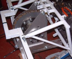
 I bolted the diff carrier back together and fixed it in place on the engine mount. The design that I did the CAD for a while ago called for a 5mm spacer on either side of the top fixing; I had decided that using shims, or similar, would make sense to be able to align things properly. As it was after much time with a straight edge between the drive and driven sprockets I ended up with a 4.5mm spacer and a 5.5mm one. That’s pretty good, I reckon.
I shortened the old chain that I’d got from Andy for alignment purposes and put it all in position. Things certainly go round and round in a pleasant sort of roundy way. Mind you, the chain makes a sort of thunk, thunk, thunk noise as the links hit the teeth on the drive sprocket. I assume that that’s what bike chains do, although not without me taking various things to bits to make sure that nothing was hitting anything.
 As well as getting the triangular side plates laser cut I also got some locating plates cut, with a curved slot for the lower corner of the triangles. However, at some point while making the various mounts I must have taken leave of my senses because I never finished off working out how, and to what, I was going to locate these. I shall have to do that now, annoying because it means that I’m going to have to do at least a little bit of welding to the chassis and engine mounts, messing up the powder coating in the process. Oh well, it was bound to happen sooner or later.
I shall probably do this next, so that I can deem the engine and transmission done.
